Pulse Oximeter
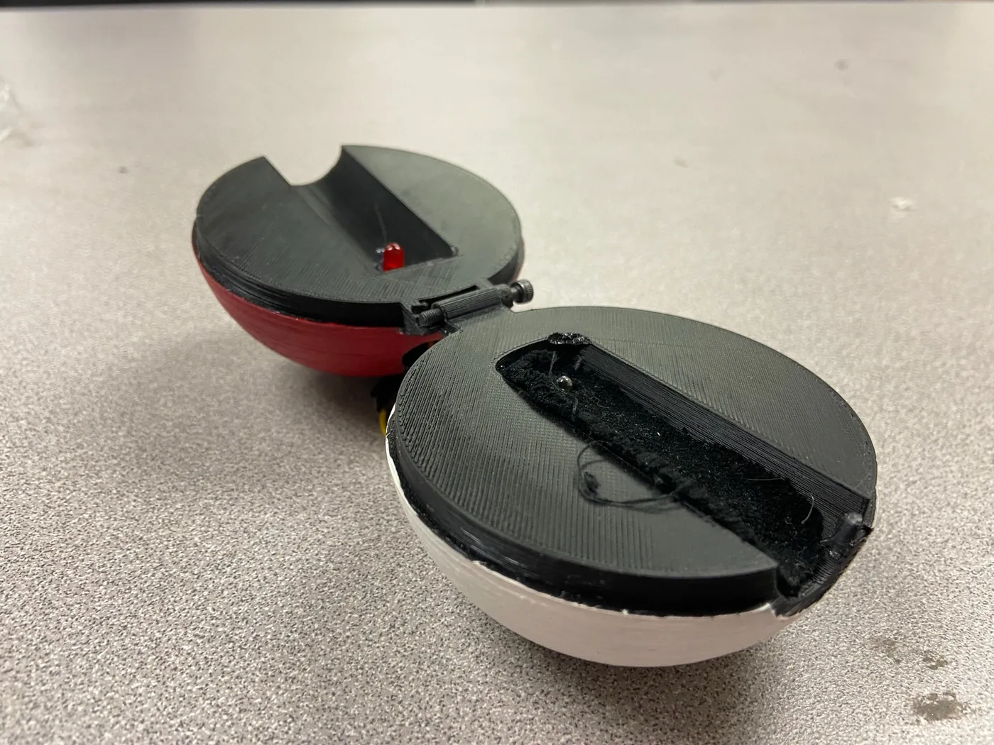
A pulse oximeter built from scratch, with a custom PCB and a Poké Ball-inspired case.
- Date
- Oct 2022 – Jun 2023
- Context
- UCLA BMES Build Team
- Discipline
- medical device development
- Stack
- Arduino Nano · MCP6041 op-amps · EAGLE PCB · Processing · Autodesk Fusion 360
- Links
- video ↗
A pulse oximeter is a medical device that measures your blood oxygen levels and pulse.
During my sophomore year, I built a pulse oximeter from scratch with a team of four, using circuitry, CAD, and software development. This project was part of the Biomedical Engineering Society (BMES) at UCLA’s Build Team technical project.
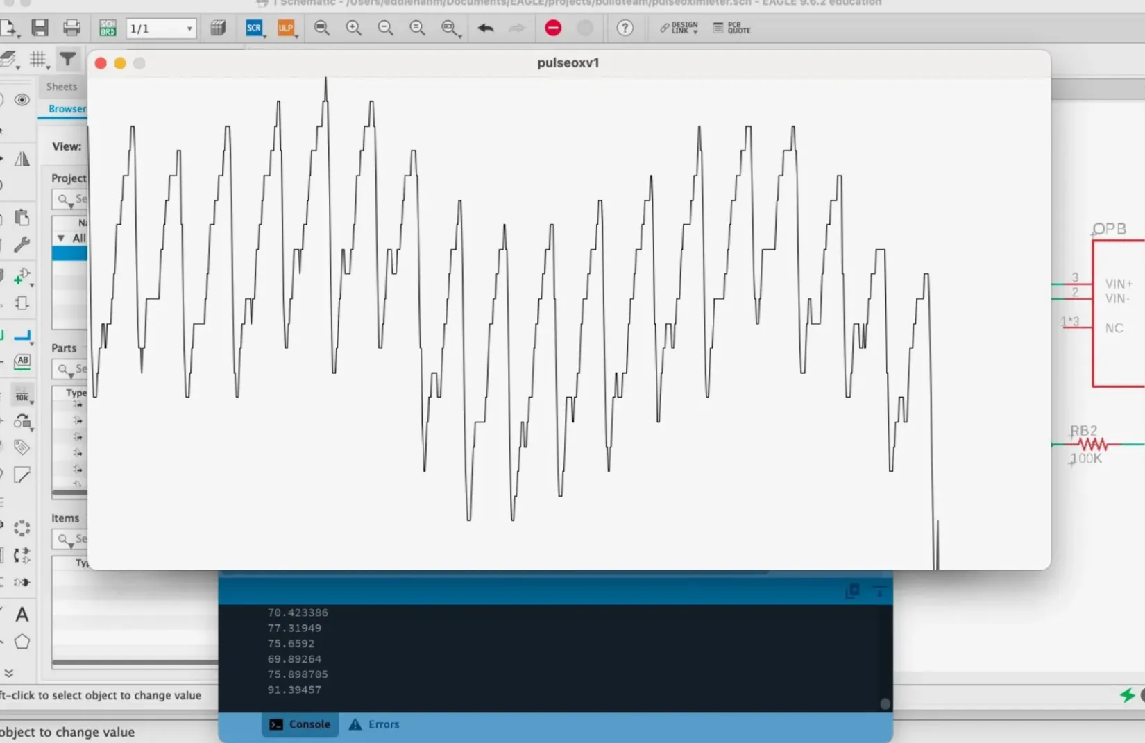
Pulse reading.
We used Processing to handle the pulse signal and display the waveform in an easily readable way. The pulse rate was calculated with a peak-detection algorithm we developed. Here’s a real-time video.
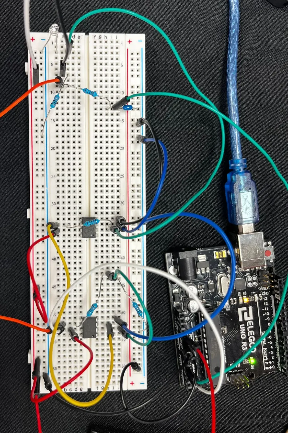
Breadboarded circuit.
To detect the pulse, we used a red LED and a photodiode to capture absorbance, which changes with blood volume in the finger. The sensing circuit amplifies the signal with MCP6041 op-amps and filters it with capacitors, with an Arduino as the microcontroller. We breadboarded it first, then recreated it in EAGLE to make a printed circuit board.
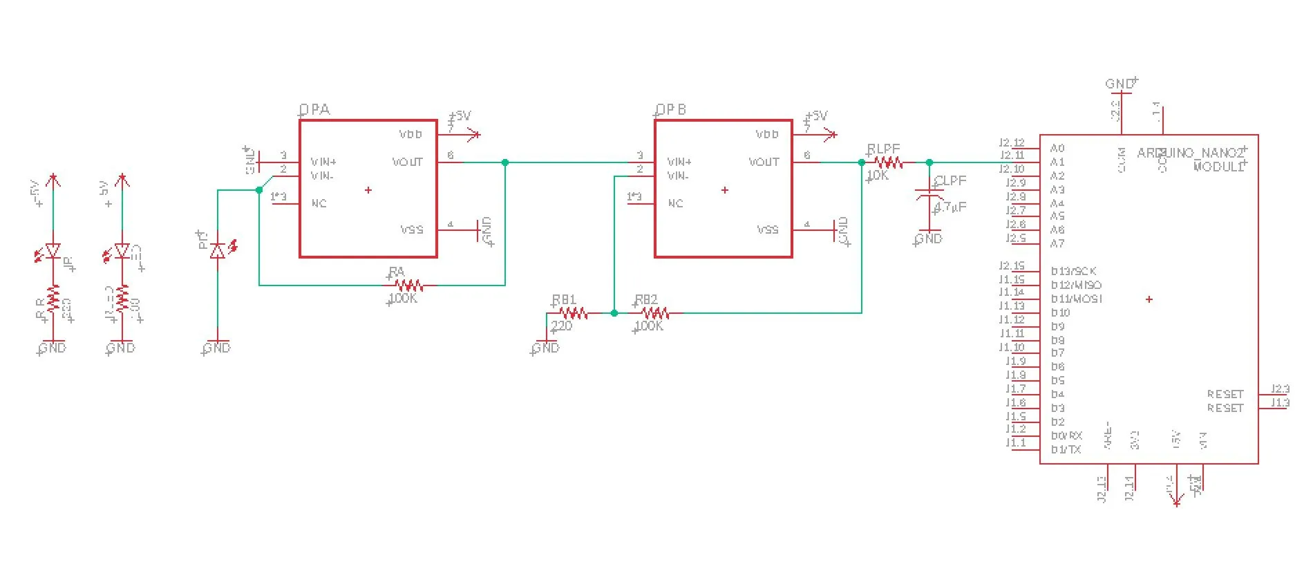
Circuit schematic.
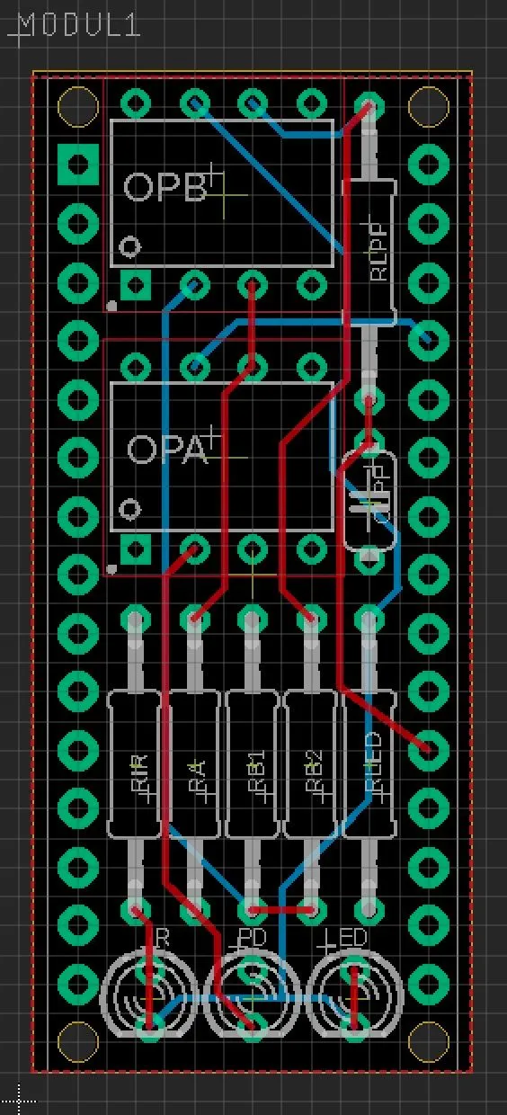
PCB design.
Once the PCB was printed, we soldered the components onto the board. The PCB was designed to sit on top of an Arduino Nano.
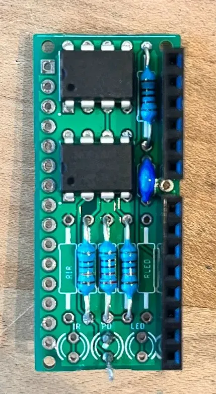
Soldering in progress.
The casing for the electronics was designed in Autodesk Fusion 360. We modeled it on the beloved Poké Ball, with a hole for users to insert their finger for a pulse reading.
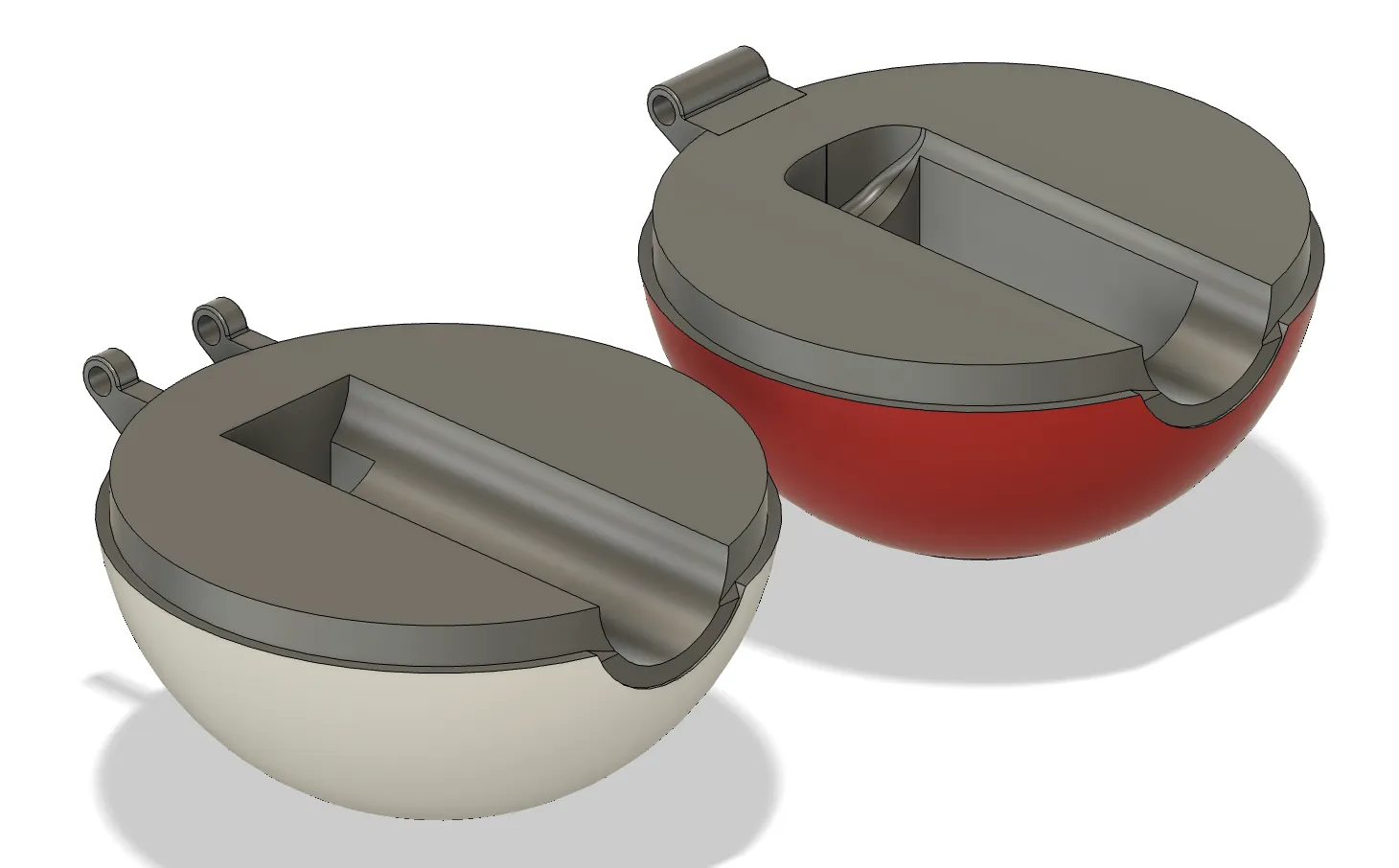
CAD of the casing.
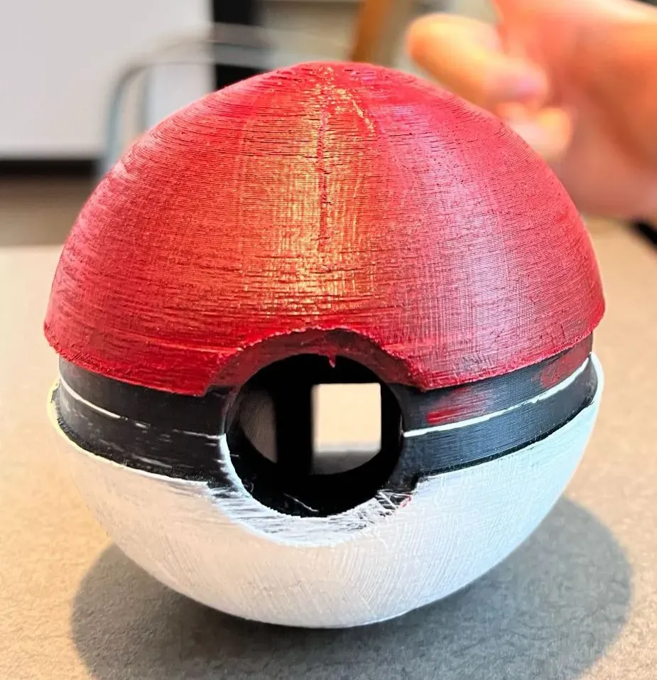
Printed model.
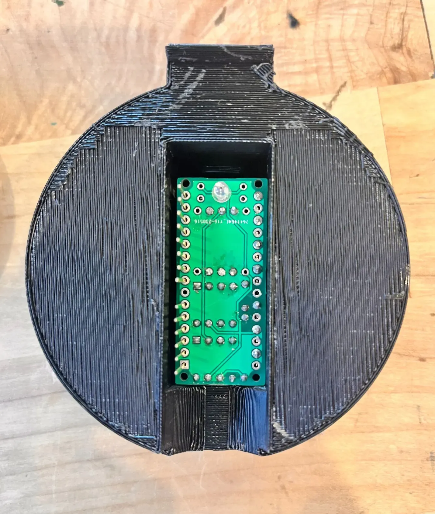
PCB inserted into the casing.
Our final device successfully read our pulse! We presented it at a Demo Day at the end of the school year alongside the other BMES technical projects.

My team at our Demo Day!